New computer on the way
Message boards :
Number crunching :
New computer on the way
Message board moderation
Previous · 1 . . . 10 · 11 · 12 · 13 · 14 · 15 · 16 . . . 19 · Next
| Author | Message |
|---|---|
 Keith Myers Keith Myers Send message Joined: 29 Apr 01 Posts: 13164 Credit: 1,160,866,277 RAC: 1,873 
|
Ok. Ok. pics when the new system is assembled. Seti@Home classic workunits:20,676 CPU time:74,226 hours   A proud member of the OFA (Old Farts Association) ID: 1939229 · |
|
Kevin Olley Send message Joined: 3 Aug 99 Posts: 906 Credit: 261,085,289 RAC: 572 
|
I've gone the opposite way, I was going to build this system into my old Coolermaster case but when I started to strip it down I decided it was a bit on the small size and ordered up the Thermaltake X71, I got it the same time as the other rad and its still sitting in its box, have not decided yet how I will rebuild this yet but thinking of a simple loop instead of the Corsair H100I which is struggling and proving to be a bit noisy, it also has enough space if I decide to throw blocks on the 1070TI's. Was a bit disappointed when I looked at my tasks and saw 3 errors, but looking at them it seems that they are faulty WU's, have finished all the WU's in W10 and when I restarted in Ubuntu I managed to generate 2 with "finish file present too long" faults. With the speed its running I have also attached Einstein and downloaded a few GPU WU's, it will take a little while for the settings in boinc to stabilise. Bed time know. Kevin   
ID: 1939230 · |
|
Grant (SSSF) Send message Joined: 19 Aug 99 Posts: 13727 Credit: 208,696,464 RAC: 304 
|
I'm happy with my Corsair Obsidian 750D Airflow series cases (just replaced the front 2 case fans to give the system with the GTX 1070s in it a bit more airflow; VRM temps dropped about 4°, GPUs same temp, but fans running slower, and CPU temp dropped about 2°). Only slightly noisier than with the supplied fans. Grant Darwin NT ID: 1939233 · |
|
Kevin Olley Send message Joined: 3 Aug 99 Posts: 906 Credit: 261,085,289 RAC: 572
|
All looking good. GKrellm monitor installed, need to play with it a bit, only problem is is there a way to make it display in 2 or columns? I am having to hide most of the processors to see the bottom of the list. I have switched over to your app_config, had to increase no of processors:-), Have also switched over to the AMD SSE41 cpu app - at first I saw the CPU times increase but after a while they dropped to below previous run times, GPU run times have also dropped, I assume that is the <-nobs> in the app_config working. Einstein timings have also dropped, 8:20 to 7:30 min, got it stabilised at a low percentage with enough in stock to keep things running if there are server problems. Kevin
ID: 1939349 · |
|
Keith Myers Send message Joined: 29 Apr 01 Posts: 13164 Credit: 1,160,866,277 RAC: 1,873
|
Hi Kevin, no I don't know anyway of making GKrellm show in two columns. Even I have troubles fitting 16 cpu windows vertically. What I normally do is go into settings and choose the Builtins >> CPU >> Apply any CPU chart config height change to all CPU charts. Then I right click a CPU chart window which pulls up its configuration drop down menu and then change the default 40 pixel height to 25 or whatever to fit all the CPU charts vertically in the desktop real estate. I don't think fitting 32 processors is going to fit at any chart height though without the charts becoming unreadable. What you could do is use the Composite CPU chart at the top to show the aggregated cpu usage. I also turn off lots of the Builtin charts that are unused like Battery, Mail, File System, Internet, Clock etc,etc. Whatever you don't need to use to reduce the number of chart windows drawn. I noticed about a 5% reduction in runtimes for the AMD compiled r3711 SSE41 app versus the Intel compiled one when I did the Lunatics benchmarks with both both apps. No reason not to use it if TBar did us a favor with a more optimized compiled one. You can also change the horizontal chart height of GKrellm too if you haven't found that setting before along with the lock the window to the last position after restart. I put the window over on the right side of my screen. Balances the Launcher/Dock on the left. Seti@Home classic workunits:20,676 CPU time:74,226 hours A proud member of the OFA (Old Farts Association) ID: 1939362 · |
|
Kevin Olley Send message Joined: 3 Aug 99 Posts: 906 Credit: 261,085,289 RAC: 572
|
Hi Keith, I had not found the width setting, it looks a lot better when widened out a bit, I have now got the composite CPU chart and for the time being reduced the number of processor charts to 8, and removed some of the other charts. How easy is it to switch monitors in the Linux environment, ATM I am running it on a 1920 x 1080 display and using a 3840 x 2160 on this machine, I have got long enough leads to swap them over fairly easily, but for the most part I will want to keep this monitor on the W10 machine. Temps are looking good, no great change from when running W10, and up-time is now about 2 days, all looking stable. Kevin
ID: 1939443 · |
|
Keith Myers Send message Joined: 29 Apr 01 Posts: 13164 Credit: 1,160,866,277 RAC: 1,873
|
It is either easy or a bit of work. Best case is the monitor is newer and exports its EDID data and gets interrogated about its capabilities at boot and everything falls into place and the display manager picks up the change and adjusts accordingly and passes the configuration through to the Xorg server which rewrites the xorg.conf. Second best is to plug the monitor in and it runs at the old monitor resolution and you use the Display app in Settings to set the new screen resolution and it adjusts things accordingly. The most work is to use the xrandr command line utility to add a new custom size to the pick list menu in the Display app. Seti@Home classic workunits:20,676 CPU time:74,226 hours A proud member of the OFA (Old Farts Association) ID: 1939452 · |
|
Kevin Olley Send message Joined: 3 Aug 99 Posts: 906 Credit: 261,085,289 RAC: 572
|
The third option sounds most useful, although I think I will try the first one first. Both screens run natively at 60 Hz but one uses Display port to use that refresh rate, if I can get it so that I can just plug and unplug and change the resolution without having to restart that will be handy. The other option is to port it across to the TV but I cannot leave it while unattended like that.(dogs). Will have a play over weekend. Kevin
ID: 1939492 · |
|
Keith Myers Send message Joined: 29 Apr 01 Posts: 13164 Credit: 1,160,866,277 RAC: 1,873
|
Let me know when you are comfortable with the system and I can provide some scripts to take the cards in P2 state and boost the clocks back to P3 state effectively. Also there is a script to set affinities and priority levels for the cpu and gpu apps. Seti@Home classic workunits:20,676 CPU time:74,226 hours A proud member of the OFA (Old Farts Association) ID: 1939513 · |
|
Kevin Olley Send message Joined: 3 Aug 99 Posts: 906 Credit: 261,085,289 RAC: 572
|
Getting used to the basics but it may take a while to get fully comfortable with it. Kevin
ID: 1939575 · |
|
Keith Myers Send message Joined: 29 Apr 01 Posts: 13164 Credit: 1,160,866,277 RAC: 1,873
|
pics!! Look at the "Whatever One" thread in the GPUUG forum. Details of my build and problems and temporary solutions. Seti@Home classic workunits:20,676 CPU time:74,226 hours A proud member of the OFA (Old Farts Association) ID: 1940008 · |
|
Kevin Olley Send message Joined: 3 Aug 99 Posts: 906 Credit: 261,085,289 RAC: 572
|
pics!! Is it in a private forum or am I looking in the wrong place? Link please. Kevin
ID: 1940063 · |
|
Keith Myers Send message Joined: 29 Apr 01 Posts: 13164 Credit: 1,160,866,277 RAC: 1,873
|
Sorry Kevin, it is a private Team forum for the GPU Users Group. You don't have access without joining the group. I'll repost my message. Well Numbkull is back online . . . . mostly. I managed to scrape the smallest possible smd resistor off a trace near the cpu socket taking the motherboard out of the old case. Actually managed to find it in the trash with all the mastic scrapings. Then wasted about 4 hours trying to solder it back in place. Finally decided to take my chances and just bridge the trace with solder. Then finally got started with the actual installation of the radiators in the new case. That was fairly straight forward except I needed to use two 90° fittings at the pump. And both leak if upset when moved. The way I mounted the pump/reservoir is in the bottom of the case and any leaks or drips is over nothing. The two 90° fittings I used on the 1080Ti Hydro Copper card were fine. So I need to order more 90° fittings and hope the new ones are better than the last. Filled the system and purged the air and then left it running overnight on the kitchen table to finish purging and look for leaks. So back to its normal spot in the cruncher bedroom and it just managed to fit on the table front to back. Turned on the system and hoped that the SMD device wasn't needed. Booted up and Windows found no network adapter. Oh-oh. Back to the BIOS to be sure it was enabled. Yes it was and back to Windows. Still no network adapter. OK, disable the onboard motherboard adapter and put a add-in network adapter in the PCIe-2 PCIeX1 slot that I used for a WiFi card originally in the machine before I wired the bedroom for hardline ethernet. That is the only open slot with 3 gpus installed. Power the system up and no POST though I hear the POST beep. Can't see the BIOS. OK, take the card out and put the WiFi card in. Same difference. Pull the network card and the machine boots to Windows no problem. So pulled the end 1070 since it was the easiest to get to and plugged in the wired Ethernet card there and I have Internet again. So I will have to run on two gpus for a while so I at least have connectivity. Also I manage to break my thermal sensor at the potted G1/4 fitting on the pump so I lost my loop temperature. At least the 1080Ti reports its temperature and since it is only water cooled at least know the ballpark loop temperature. So, will probably end up tearing the system apart again to replace the motherboard along with the cpu. Will order more 90° fittings and another G1/4 thermal sensor. I will get another Crosshair VII Hero motherboard and another 2700X, The Hero and the 2700X are so much better than either the Prime Pro and the RMA'd 1700X. Doubly so when both are combined. At least the case worked out very well as I expected. Was great working in it. So much space. As promised here are the pics. It will look the same when the motherboard and cpu gets replaced. 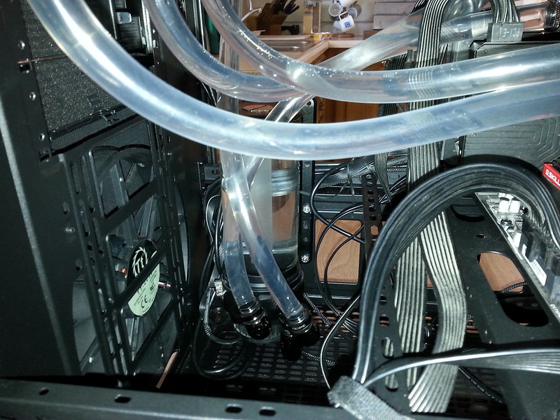 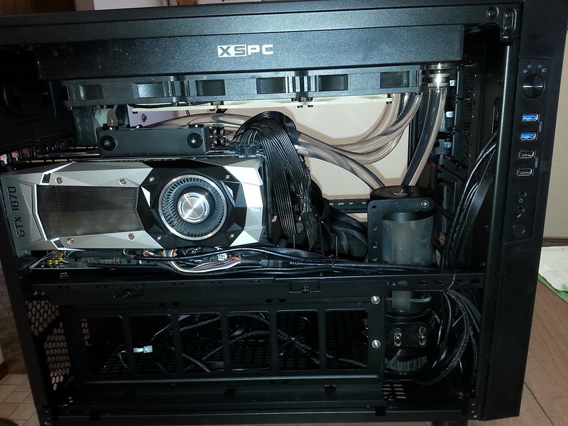 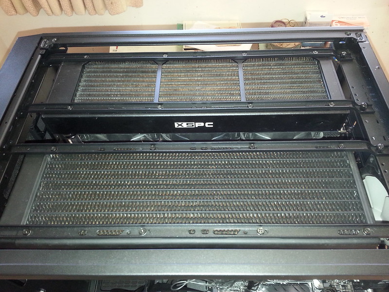 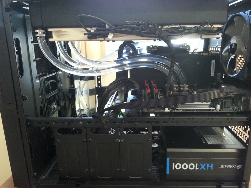 Seti@Home classic workunits:20,676 CPU time:74,226 hours A proud member of the OFA (Old Farts Association) ID: 1940076 · |
|
Kevin Olley Send message Joined: 3 Aug 99 Posts: 906 Credit: 261,085,289 RAC: 572
|
That does look roomy, I thought mine did until I started putting bits into it. The mistake I made was to buy everything in one hit when I did not know the sizes of certain parts or the restrictions of the case. That's why I have got the X71 but have not yet decided exactly how I am going to upgrade this system, position wise I need a fairly thin case. Re-soldering modern electronics is not easy, was you trying to use a regular iron or a hot air soldering iron and paste? I was originally looking at Thermaltake The Tower for the Threadripper but too much glass that near the floor with my mutts around, its not unknown for Toby to come charging in with a bone in his mouth:-) Kevin
ID: 1940233 · |
|
Keith Myers Send message Joined: 29 Apr 01 Posts: 13164 Credit: 1,160,866,277 RAC: 1,873
|
I was first trying to use my gas soldering iron with heat shrink tip at first which works similar to a hot air iron in practice. I have used it in the past on larger SMD devices successfully. But this device was only about 0.5mm and didn't present a big enough surface area to accumulate enough heat to melt the solder on its ends. After trying and failing for several hours I got out my normal Hakko soldering station with the needle tip and just bridged the trace. I never got around to purchasing a proper SMD workstation because I never really got started with that technology as it ramped up and my work life ended. What I like about the Thermaltake Core series is that the side panels are interchangeable. You can switch the acrylic panel from left to right and vice versa for the perforated panel. I actually purchased an additional perforated panel for my X9 case so I have perforated panels on both sides as well as the normal top panel. I might do the same for the X5 case. Right now with the missing 1070 on the outside PCIe slot I can get away with the standard acrylic panel on the left. Once I rebuild it again and get the second 1070 card back in I will be switching the acrylic panel to the right side which is against the wall and not normally visible anyway. That way the end card can get some extra air into its blower fan other than what it draws in from the front. The top 1070 near the cpu ends up the hottest card in all my systems normally. Seti@Home classic workunits:20,676 CPU time:74,226 hours A proud member of the OFA (Old Farts Association) ID: 1940234 · |
rob smith  Send message Joined: 7 Mar 03 Posts: 22184 Credit: 416,307,556 RAC: 380
|
Re-soldering modern electronics is not easy, was you trying to use a regular iron or a hot air soldering iron and paste? That all depends on what is being worked on. For SMDs I am lucky in having access to professional standard spot heaters, thermal masks etc. which make life so much easier than any other approach (I've tried them all). Obviously when using this sort of kit one can only use paste and flux masking. For stand-alone devices it all depends on the size - I've a range of soldering irons (5W up to 350W) and tips from 0.25mm to 10mm (needless to say some tip/iron combinations don't play well!), the form of the solder depends on what I'm working on, and how many joints I have to do - repairing a 48-pair mulit-way cable is a very different operation to replacing an SoT calibration resistor. Bob Smith Member of Seti PIPPS (Pluto is a Planet Protest Society) Somewhere in the (un)known Universe? ID: 1940238 · |
|
Kevin Olley Send message Joined: 3 Aug 99 Posts: 906 Credit: 261,085,289 RAC: 572
|
Rob, My experience is totally amateur, learned some of the basics when in my teens and still do the occasional basic work when needed. About 20 years back was working for someone that that was buying and selling 2nd hand telephone equipment, mainly large office type stuff, the systems as well as the phones themselves. In my spare works time I was testing and doing basic repair work and it sort of expanded from there, a lot of the work was basic swapping of components - but down to SMD level, as long as the boss was seeing a return he was happy and willing to invest in any basic tools needed, I ended up leaving when he started to expect too much and he was not quite willing to pay me what it was worth, apart from that he was starting to keep me off the road to much.(truck driver at heart). I had noticed that things have shrunk even further since then and to be honest I would not like to try to work down to that level. Kevin
ID: 1940360 · |
|
Keith Myers Send message Joined: 29 Apr 01 Posts: 13164 Credit: 1,160,866,277 RAC: 1,873
|
That was the smallest SMD device I had ever tried to work with. Couldn't really see it with the naked eye. I was using a 20X joulers loupe just to find it on the motherboard and try positioning it over its original landing position on the trace. If I had had proper solder paste and a hot iron or tweezers, I'm sure I could have replaced it. My background was 20 years of depot level board repair but almost exclusively through-hole construction. The boards at the tale end of my career were just starting to transition to SMD componentry. I wish I had kept up with the technology since that is the way of the world now except for high power stuff nowadays. Seti@Home classic workunits:20,676 CPU time:74,226 hours A proud member of the OFA (Old Farts Association) ID: 1940374 · |
|
Grant (SSSF) Send message Joined: 19 Aug 99 Posts: 13727 Credit: 208,696,464 RAC: 304
|
 This was the type of component I was having to deal with around the time I left my job in the repair industry. At that time we didn't have a hot air reworking station- it was soldering iron, wick and very fine jewellers drivers to remove & replace the components. And no, the tip in the image wouldn't be of any use for soldering the new component on, it's probably at the start of unsoldering the pins before removing the IC. It was pretty rare (out of total repairs) to have to replace such an IC; the fact is (or was) they are extremely reliable. Most such replacements were required due to power supply faults, or power surges/lightning strikes.  Components such as these required replacement more frequently, once again they themselves generally didn't fail- but when the components they were driving died, they often got taken out as well.  Surface mount components such as these were the main items requiring replacement. The resistors & capacitors themselves would often give problems (relatively speaking). Thermal cycling & pcb movement resulting in cracking of the component (sometimes visible, mostly not- the failure was internal).  The old style components were a lot easier to replace, not to mention actually fault find with a multimeter or CRO. Checking voltages or waveforms on components such as the IC i first posted is a real bugger to make sure you don't short something out & make it worse, while trying to track down what's wrong. Grant Darwin NT ID: 1940379 · |
|
Kevin Olley Send message Joined: 3 Aug 99 Posts: 906 Credit: 261,085,289 RAC: 572
|
The quad packages are no fun, so easy to damage the track pads when trying to remove them, the ones that the legs curled underneath them were also a pain. The DIL's are easier but still need a very steady hand. What I have noticed when handling some of the latest boards though is that the sizes of some of the caps and resistors has shrunk again and some IC's are now using an even closer leg spacing. I was also seeing a lot of ceramic? sub boards in DIL or SIL through board designs, had to be handled carefully it was easy to de-solder the wrong end of the pin. Fault finding could be a problem, but luckily I did not have to do too much of that, most of the boards that I was working on were line cards normally 8 or 16 identical circuits on a card, If a circuit went down when a system was in use they just used to transfer that circuit to another circuit or card, when buying old systems you would quite often find several cards with faulty circuits. A card with a circuit down was worthless, manufacturers would not repair faulty cards they would only sell new ones and they were not cheap, and even technical info about cards was unavailable, even some of the components were unavailable or so they thought:-) Recovering parts from working circuits on faulty cards I was getting a 50% to 70% success rate at repairing cards, Not bad for an amateur that did not even understand most of the circuitry I was working on. Most of the work was done with a hot air reworking station, vacuum desoldering iron and a couple of fine temp controlled irons with an assortment of tweezers, knifes and screwdrivers used as pry-bars. One thing that got me was about this time on the computer side of things the phrase "plug and play" was coming into use, on these phone systems the line cards both phone and exchange line were all hot plugged and had been for ages, you did not need to shut a complete system down to change a card, on some of the larger newer systems that had multiple redundant control systems you could even change a processor card without downing the system. @ Keith, everything running fine but time is a little short in my schedule so have not had much time to play with Linux. Kevin
ID: 1940444 · |

©2024 University of California
SETI@home and Astropulse are funded by grants from the National Science Foundation, NASA, and donations from SETI@home volunteers. AstroPulse is funded in part by the NSF through grant AST-0307956.